
Choosing the Right Mobile Robot Simulation Tools
Picking the right simulation software is a big first step when you’re getting into mobile robotics. It’s not just about making a virtual robot move; it’s about creating a realistic environment to test your ideas before you even touch real hardware. There are a few big names out there that most people end up looking at.
Overview of Popular Simulators: Gazebo, Webots, and CoppeliaSim
These three are probably the most common choices. Each has its own strengths and weaknesses, so what’s best really depends on what you’re trying to do.
- Gazebo: This one is really popular, especially if you’re already using ROS (Robot Operating System). It’s known for being pretty powerful and can handle complex environments with lots of sensors. It’s got a good physics engine, which means your robot’s interactions with the world feel more real. It’s a solid choice for serious research and development.
- Webots: Webots is another strong contender. It’s got a nice graphical interface and supports a wide range of robots and sensors right out of the box. It’s often praised for being easier to get started with than Gazebo, and it’s also cross-platform, which is handy.
- CoppeliaSim (formerly V-REP): This simulator is really flexible. You can use it for everything from simple setups to very complex industrial simulations. It has a lot of built-in features and supports many programming languages, giving you a lot of control over how you build and test your robots.
Integrating Motion Planning with MoveIt!
Once you have your robot model and a simulator, you’ll likely want to figure out how your robot moves around, especially if it has arms or needs to navigate tricky spaces. That’s where MoveIt! comes in. It’s a software framework that works really well with ROS and helps you plan how your robot’s arm or base will move from point A to point B without bumping into things. It handles all the complex calculations so you don’t have to.
Leveraging ROS for Simulation Frameworks
ROS is kind of the glue that holds a lot of this together. It’s not a simulator itself, but it provides a way for different software components – like your robot’s control code, sensor drivers, and the simulator – to talk to each other. Using ROS means you can often swap out one simulator for another without rewriting all your robot’s brain. It makes your simulation setup much more adaptable and easier to manage in the long run.
Building and Modeling Your Mobile Robot
Alright, so you’ve got your simulation environment picked out, and you’re ready to start bringing your robot to life in the digital world. This is where the rubber meets the road, so to speak, when it comes to making your robot behave the way you want it to. We’re talking about creating the digital blueprint of your robot, making sure it has the right shape, the right parts, and the right way of moving.
Creating Robot Models for Simulation
Think of this as building your robot from scratch, but with code and 3D files instead of nuts and bolts. You need to define everything: its physical dimensions, how its joints connect, and what kind of sensors it has. This usually involves creating URDF (Unified Robot Description Format) files. These files are basically XML documents that describe your robot’s structure. It’s not just about looks; the physics engine in your simulator needs this information to know how your robot will interact with the world. Getting the model right is super important because it directly affects how your robot will behave later on.
Here’s a quick rundown of what goes into a robot model:
- Links: These are the rigid parts of your robot, like the chassis, wheels, or arms. You define their size, shape, and mass.
- Joints: These connect the links and define how they can move relative to each other. You’ll specify the type of joint (e.g., revolute for rotation, prismatic for sliding) and its limits.
- Inertial Properties: This is about how mass is distributed, which affects how the robot moves and reacts to forces.
- Visual and Collision Properties: These define how the robot looks in the simulation and what parts of it should interact physically with the environment.
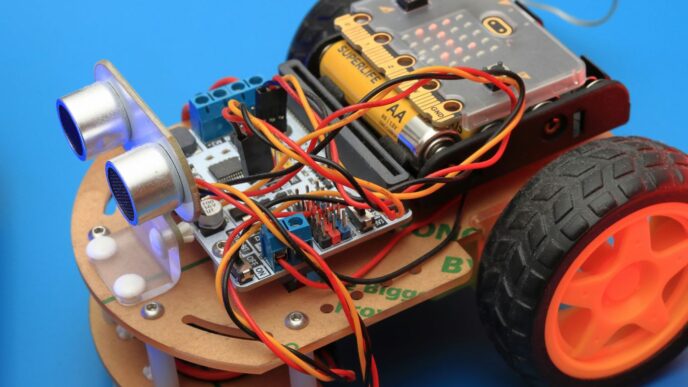
Simulating Differential Drive Mobile Robots
Differential drive robots are pretty common, especially for indoor navigation tasks. They’ve got two independently driven wheels, and they steer by changing the speed of these wheels. It’s like a tank, but usually with wheels. When you’re modeling one of these, you’ll focus on the chassis (the main body) and the two drive wheels. The URDF will describe these components and how they’re connected. The key here is to accurately represent how the robot moves based on the wheel speeds. This means defining the robot’s base link and then attaching the wheels to it with appropriate joints. The simulator will then use this information, along with commands you send to the wheels, to calculate the robot’s position and orientation in the virtual environment.
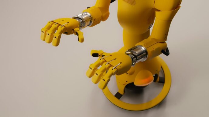
Working with 7-DOF Robotic Arms in Simulation
Now, if you’re dealing with something more complex, like a 7-Degrees-of-Freedom (DOF) robotic arm, the modeling gets a bit more involved. Each DOF represents a way the arm can move, usually a joint. So, a 7-DOF arm has seven joints that can be controlled independently. This gives it a lot of flexibility, allowing it to reach around obstacles and get into tight spots. When you’re modeling this, you’ll have a chain of links and joints, starting from a base and extending out to the end-effector (the gripper or tool). Each joint needs to be defined with its type, limits, and how it connects to the next link. This detailed model is absolutely critical for motion planning, which we’ll get to later. Without an accurate model, tools like MoveIt! wouldn’t know how to command the arm to perform specific tasks. You’ll spend a good chunk of time getting these models just right, especially if you’re working with real-world hardware, to make sure the simulation matches reality as closely as possible.
Implementing Autonomous Navigation in Simulation
So, you’ve got your robot model all set up and maybe even figured out how to make it move around a bit. That’s cool, but the real magic happens when you get it to navigate on its own. This is where autonomous navigation comes in, and it’s a pretty big deal for making robots actually useful.
SLAM and AMCL for Mobile Robot Localization
First off, a robot needs to know where it is. It’s not like us humans who just know we’re in our living room. For a robot, this is a problem called localization. A super common way to tackle this is using something called SLAM, which stands for Simultaneous Localization and Mapping. Basically, the robot builds a map of its surroundings while figuring out its own position on that map at the same time. Pretty neat, right?
Once you have a map, you need a way to pinpoint the robot’s location on it. That’s where AMCL, or Adaptive Monte Carlo Localization, comes into play. It’s a probabilistic method that keeps track of where the robot might be, updating its guess as it gets new sensor data. It’s good because it can handle noisy sensor readings and even recover if the robot gets a bit lost.
Here’s a simplified look at the process:
- Mapping Phase: The robot explores an area, using sensors like LiDAR or cameras to build a map. SLAM algorithms are key here.
- Localization Phase: With a map in hand, the robot uses AMCL to figure out its precise spot on that map.
- Continuous Refinement: AMCL constantly refines the robot’s estimated position as it moves and gathers more sensor information.
Developing Navigation Strategies with ROS Navigation Stack
Okay, so the robot knows where it is. Now, how does it get from point A to point B without bumping into things? This is where the ROS Navigation Stack shines. It’s a collection of tools within ROS that handles path planning and obstacle avoidance.
Think of it like this: you tell the robot a goal location, and the Navigation Stack figures out the best route. It uses different components:
- Global Planner: This creates a general, long-term plan from the robot’s current location to the goal, often using the map.
- Local Planner: This handles the immediate movements, making sure the robot avoids obstacles in real-time and follows the global plan as closely as possible. It’s the part that actually steers the robot.
- Costmaps: These are like internal maps that represent obstacles and free space, helping the planners make safe decisions.
Simulating Autonomous Movement in Complex Environments
Putting all this together in a simulator is where you can really experiment without breaking anything. You can create intricate environments with tight corners, dynamic obstacles, and different floor surfaces. Simulators like Gazebo or Webots let you test how your SLAM, AMCL, and Navigation Stack configurations perform under various conditions.
For instance, you might want to see how well your robot can map a cluttered room or navigate a narrow hallway. You can change sensor noise levels, robot speeds, and even introduce unexpected events to see how robust your navigation system is. This iterative process of testing, tweaking, and re-testing in simulation is super important before you even think about putting your code on a real robot.
Advanced Simulation Techniques and Integrations
Okay, so we’ve covered the basics of setting up simulations and getting robots moving. But what if you want to get more serious, more realistic? That’s where these advanced techniques come in. It’s all about making your simulated robot act and react like it’s the real deal, and connecting it to other systems you might be using.
Interfacing Sensors and Actuators in Mobile Robot Simulation
This is where things get interesting. Your robot isn’t just a model; it needs to ‘see’ and ‘do’ things. We’re talking about hooking up simulated sensors – like cameras, LiDAR, or even just simple bump sensors – and making sure they send data back to your robot’s brain (the control software). Likewise, actuators, like motors for wheels or joints for arms, need to receive commands. Getting this two-way communication right is key to a believable simulation. You’ll often use ROS topics and services for this, publishing sensor data and subscribing to motor commands. It’s like giving your robot a virtual nervous system.
ROS for Aerial Robot Simulation
Flying robots, or drones, have their own set of challenges. Simulating them involves different physics – think aerodynamics, wind effects, and battery life. ROS has good support for this, often using specific packages designed for UAVs. You’ll be dealing with things like attitude control (pitch, roll, yaw) and altitude hold. It’s a bit different from ground robots, but the core ROS principles still apply. You can simulate flight paths, test navigation algorithms in 3D space, and even simulate sensor payloads like cameras for aerial mapping.
Bridging Simulation with MATLAB and Simulink
Sometimes, you’ve got existing code or specific analysis tools in MATLAB or Simulink that you want to use with your robot simulation. This is where bridging comes in. You can set up connections so that your ROS simulation can send data to, or receive commands from, MATLAB/Simulink. This is super handy if you’re doing a lot of control system design or data analysis. For example, you might run a complex control algorithm developed in Simulink and have it control your simulated robot through ROS. It opens up a lot of possibilities for testing and validation using tools you’re already comfortable with.
Best Practices for Effective Mobile Robot Simulation
Alright, so you’ve spent a good chunk of time building your robot in simulation. That’s awesome! But just because it works in the digital world doesn’t mean it’s ready for the real deal. We need to be smart about how we simulate to make sure our robots actually do what we expect when they leave the computer. It’s not just about making pretty 3D models; it’s about making sure the simulation is useful.
Optimizing Simulation Performance
Nobody likes waiting around for a simulation to catch up. Slow simulations mean less testing, which means more headaches later. So, how do we speed things up?
- Keep it simple when you can: Don’t load your simulation with super high-resolution textures or overly complex meshes if your robot doesn’t need them. Think about what’s actually important for the task you’re testing. A detailed model of a coffee mug is probably not necessary if your robot is just trying to avoid walls.
- Tune your physics engine: Most simulators have physics engines. Playing with the settings here can make a big difference. Things like the number of contact points or the simulation step size can be adjusted. Just be careful not to change them so much that the physics becomes unrealistic.
- Use efficient algorithms: When you’re dealing with things like sensor data or path planning within the simulation, make sure the code you’re using is as efficient as possible. This is where things like ROS nodelets can really help by keeping processing on the same machine.
Hardware-in-the-Loop Simulation
This is where things get really interesting. Hardware-in-the-loop, or HIL, means you’re connecting your actual robot hardware – like the main computer or specific sensors – to the simulation. It’s like giving your robot a virtual playground to test its real brain.
This approach helps bridge the gap between pure simulation and real-world deployment. You get to test your actual control code on the real hardware, but in a controlled, safe simulated environment. This is super useful for testing things that are hard to replicate or dangerous to try out on a physical robot, like emergency stop routines or high-speed maneuvers.
Troubleshooting Common Simulation Issues
Even with the best practices, things go wrong. Here are a few common culprits:
- Model inaccuracies: Your robot model in the simulator might not perfectly match the real robot. This could be due to incorrect dimensions, mass properties, or joint limits. Always double-check your URDF or SDF files.
- Sensor noise and limitations: Real sensors aren’t perfect. They have noise, limited range, and specific fields of view. If your simulation doesn’t account for these, your localization or perception algorithms might fail when they hit the real world. Try to add realistic noise to your simulated sensor data.
- Timing and synchronization problems: Sometimes, the timing of messages between different parts of your robot’s software can be off in simulation, leading to unexpected behavior. This is especially true when interfacing with external hardware. Make sure your ROS message timestamps are handled correctly.
Getting simulation right takes practice, but it’s totally worth it. It saves time, money, and a lot of potential frustration when you finally deploy your robot.
Real-World Deployment from Simulation
So, you’ve spent ages tweaking your robot in simulation, getting everything just right. Now comes the big moment: moving it out into the real world. It’s not always as simple as hitting a button, you know. There’s a gap between what you see on your screen and what happens with actual hardware. Bridging this gap is where the real challenge lies.
Transitioning from Simulation to Physical Robots
Think of simulation as a practice run. You’ve ironed out the bugs, tested different scenarios, and feel confident. But the physical world has its own quirks. Sensors aren’t perfect, motors have limits, and the environment itself can be unpredictable. You need a plan to make that jump.
Here’s a rough idea of what that transition might look like:
- Model Verification: Double-check that your robot’s physical dimensions, sensor placements, and actuator limits in the simulation match the real thing as closely as possible. Small discrepancies can cause big problems.
- Parameter Tuning: Simulation parameters often need adjustment for real-world use. Things like PID controller gains for motors, sensor noise levels, and even communication delays might need fine-tuning.
- Incremental Testing: Don’t just upload your entire simulated program and hope for the best. Start with basic movements, then gradually add complexity. Test individual components before integrating them all.
- Safety First: Always have a way to stop the robot quickly. This might be an emergency stop button or a remote kill switch. You don’t want your creation to cause damage or hurt anyone.
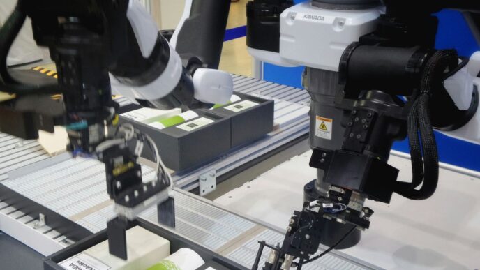
ROS-Industrial for Real-World Robot Control
When you’re dealing with industrial robots, things get a bit more specialized. That’s where ROS-Industrial comes in. It’s basically an extension of ROS that’s built to work with the kind of robots you find on factory floors – think big robotic arms doing repetitive tasks. It helps connect ROS to the specific hardware and communication protocols these industrial machines use. This means you can use all the cool ROS tools you learned in simulation, like motion planning with MoveIt!, to control actual industrial robots.
Validating Simulation Models with Real-World Data
This is super important. You can’t just assume your simulation is perfect. You need to prove it. The best way to do this is by comparing how your robot behaves in simulation to how it actually behaves in the real world.
Here’s a simple way to think about it:
- Run a test in simulation: Perform a specific task, like moving from point A to point B.
- Record the data: Note down things like the path taken, time taken, and any errors encountered.
- Run the same test on the physical robot: Try to replicate the exact same task.
- Compare the results: Look at the data from both. Are the paths similar? Is the timing off? Are there unexpected behaviors?
| Metric | Simulation Result | Real-World Result | Difference | Notes |
|---|---|---|---|---|
| Travel Time | 5.2 seconds | 6.1 seconds | 0.9 sec | Motor speed differences |
| Path Deviation | 0.5 cm | 2.1 cm | 1.6 cm | Wheel slippage, uneven floor |
| Task Completion | Success | Success | N/A | Both completed the objective |
If you see big differences, it’s a sign that your simulation model needs more work. You might need to adjust friction, add more realistic sensor noise, or refine the robot’s dynamics. It’s an iterative process, but getting this validation right is key to trusting your simulation for future development.
Wrapping Up Your Simulation Journey
So, we’ve gone through a bunch of tools and ways to get your mobile robots simulated. It’s not always a walk in the park, and sometimes things get a bit messy, just like trying to fix something yourself when you’re not really sure what you’re doing. But by picking the right simulators, understanding how to set them up, and following some good practices, you can really make your robot development process smoother. Think of it as building a solid foundation before you start constructing the actual building. Getting this right means fewer headaches down the road when you’re trying to get your robot to do its thing in the real world. Keep practicing, keep experimenting, and you’ll get there.